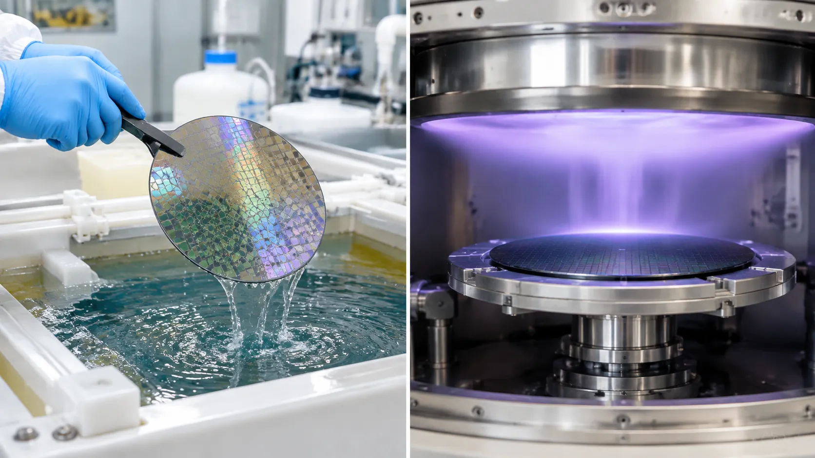
Balancing cleanroom throughput with strict yield limits is tough—especially when chemical loading effects can make or break your wafer uniformity.
So, what is the typical batch size wet etch semiconductor fab tools actually run today?
Whether you are sizing carriers for a legacy 200mm wet bench or optimizing dual-cassette automation on an advanced 300mm line, getting this balance right is critical for tool uptime and cycle times. In this guide, you will learn the standard batch capacities used across commercial fabs, the critical trade-offs between 25-wafer lots and large chemical baths, and when moving to single-wafer tools makes sense.
Let's dive right in.
Typical Batch Size Wet Etch Semiconductor Fab Standards Across Wafer Sizes
When process engineers evaluate the typical batch size wet etch semiconductor fab operations rely on, the standard configuration centers on multiples of 25 wafers. In our cleanroom experience, matching your wafer cassette capacity to your chemical bath volume is the fastest way to stabilize fab wafer throughput while keeping your cost of ownership (CoO) in check.
| Wafer / Substrate Type | Standard Batch Size | High-Throughput Configuration | Primary Handling Method |
|---|---|---|---|
| 150mm & 200mm Silicon | 25 Wafers | 50 Wafers (Dual Cassette) | Open Cassette / SMIF |
| 300mm Silicon | 25 Wafers | 50 Wafers (Half-Pitch) | Automated FOUP |
| GaAs, SiC, & GaN | 10 to 25 Wafers | Custom Lot Sizing | Dedicated / Low-Mass Carriers |
150mm and 200mm Legacy Fab Cassette Capacity (25 vs 50 Wafers)
In legacy 150mm and 200mm lines, the 25-wafer standard carrier is the universal baseline. Depending on process tolerances and line balance, we deploy two primary configurations:
Single-Cassette Runs (25 Wafers): Best for tight process windows where chemical uniformity is critical.
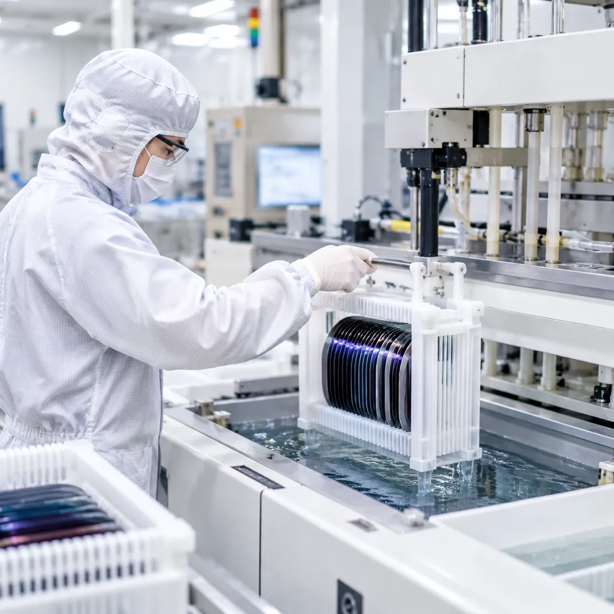
Dual-Cassette Runs (50 Wafers): We place two 25-wafer cassettes side-by-side or end-to-end inside a single tank. This doubles wafers per hour (WPH) throughput without expanding the wet chemical process bench footprint.
300mm Automated FOUP Handling and 50-Wafer Half-Pitch Batch Processing
At 300mm nodes, manual handling disappears in favor of FOUP load port automation. While a standard FOUP holds 25 wafers, running single lots on a massive automated wet bench rarely meets aggressive throughput targets.
Lot Combining: Automated load ports extract wafers from two separate 25-wafer FOUPs simultaneously.
Half-Pitch Interleaving: We interleave two lots into a single 50-wafer half-pitch batch, cutting the spacing between wafers in half. This maximizes tank utilization and keeps chemical consumption per wafer low.
Carrierless Immersion Wet Station vs Standard 25-Wafer Carrier Setups
Choosing whether to submerge the plastic cassette directly into the acid tank changes your bath dynamics completely:
Standard 25-Wafer Carrier Setups: Wafers stay inside PTFE or PFA cassettes throughout the process. It offers simple robotics, but the bulky carrier traps chemicals and increases carry-over between tanks.
Carrierless Immersion Wet Station: Wafers are lifted out of the transport cassette and held by a low-profile quartz or PEEK chuck during immersion. Removing the heavy carrier slashes chemical drag-out, improves laminar flow across the wafer surface, and reduces DI water rinse times.
Compound Semiconductor Fab Batch Sizing for GaAs, SiC, and GaN Substrates
Compound substrates do not always follow standard silicon rules. When we configure a semiconductor wet station for 100mm or 150mm compound materials, batch sizes are tailored to substrate fragility and wafer cost:
Gallium Arsenide (GaAs): Extremely brittle. We frequently reduce batch sizes to 10 to 25 wafers with wider slot pitches to prevent mechanical vibration and wafer breakage.
Silicon Carbide (SiC) & Gallium Nitride (GaN): Generally run in 25-wafer cassettes, though high substrate value often dictates smaller, custom-spaced lots during aggressive wet etching to eliminate any risk of whole-lot scrap.
Chemical and Fluid Dynamic Constraints Governing Batch Sizing
Boundary Layer Dynamics and Laminar Flow
Wafer pitch directly affects fluid movement. As spacing tightens—especially in 50-wafer half-pitch setups—the boundary layer of stagnant liquid against each substrate thickens relative to the gap:
-
- Fluid stagnation: Without sufficient flow velocity, fresh chemical cannot penetrate the tight gaps between wafers.
- Flow uniformity: Recirculation manifolds must supply uniform, upward laminar flow to wash the entire surface evenly from bottom to top.
- Surface entrapment: Narrow channels increase viscous drag, slowing down the exchange rate of active reactants at the wafer center.
Chemical Loading Effect and Reactant Starvation
In dense wafer batches, large total surface areas consume active etchants rapidly. This triggers localized chemical loading effects:
-
- Radial non-uniformity: Reactants deplete faster before reaching the center of closely spaced wafers, creating higher etch rates at the wafer perimeter.
- Bath turnover requirements: We design our recirculation systems for rapid bath volume turnover, preventing active species depletion across high-surface-area loads.
- Process matching: Implementing balanced flow dynamics in our chemical wet bench for wafer cleaning and etching ensures that active chemical concentrations remain identical across every slot in the carrier.
Managing Exothermic Temperature Spikes
Aggressive acid chemistries—such as hot phosphoric acid for silicon nitride strips or sulfuric-peroxide mixes—generate significant exothermic heat during reactions.
-
- Localized thermal runaway: High wafer density concentrates the heat generated per cubic centimeter of bath volume, creating micro-zones of elevated temperature.
- Etch rate skewing: Because etch rates jump exponentially with temperature shifts, uneven heat dissipation causes severe wafer-to-wafer variation.
- Inline thermal stabilization: Maintaining tight batch tolerances requires inline heat exchangers and precision temperature feedback directly in the process tank weir.
Chemical Drag-Out Mitigation in the Quick Dump Rinser (QDR)
Moving dense wafer carriers from an aggressive chemical bath to a quick dump rinser (QDR) carries substantial chemical volume trapped between tightly spaced substrates:
| Batch Loading Factor | Operational Challenge | Engineering Solution |
|---|---|---|
| Meniscus Retention | High chemical volume clings between tightly spaced wafers. | Slow robotic lift speeds coupled with nitrogen knives to shear liquid films before transfer. |
| Rinse Tank Acidification | Heavy chemical drag-out rapidly lowers QDR water purity. | High-flow bottom fill manifolds and rapid pneumatic bottom dump valves to clear acidic water in seconds. |
| Particle & Watermark Risk | Residual etchant continues reacting during slow rinse transitions. | Synchronized top-spray nozzles that flood wafer surfaces instantly upon tank entry. |
Batch Wet Etch vs Single-Wafer Processing: Fab Trade-Offs
Deciding on the typical batch size wet etch semiconductor fab setup comes down to balancing wafer throughput, yield security, and process precision. When we help engineering teams evaluate a batch immersion vs single-wafer wet processing comparison, we look directly at four operational realities on the cleanroom floor.
Wafers Per Hour (WPH) Throughput vs Overall Cost of Ownership (CoO)
High-volume manufacturing relies on keeping cost of ownership (CoO) down while pushing wafers per hour (WPH) throughput up.
-
- Footprint Efficiency: Processing 25 or 50 wafers simultaneously in an automated wet bench delivers massive WPH per square meter compared to multi-chamber single-wafer platforms.
- Chemical Consumption: Batch tanks reuse recirculated, filtered chemistries across multiple lots, drastically cutting chemical and DI water volume per wafer.
- Long-Cycle Economics: If an etch or strip takes more than 3 minutes, single-wafer tools create severe bottlenecks unless you invest in expensive, high-chamber-count systems.
Lot Scrap Risk Management and Catastrophic Batch Loss Exposure
The biggest operational pushback against high-capacity batching is catastrophic batch loss exposure.
-
- Batch Scrap Risk: If a chemical spike goes wrong, a bath gets contaminated, or a robot handoff fails in a 50-wafer bath, you lose up to two full FOUPs at once.
- Single-Wafer Containment: Single-wafer processing isolates risk to one substrate at a time, making it the safer bet for high-value, late-stage wafers with dozens of completed mask layers.
- Cross-Contamination: In batch immersion, particles lifted from one wafer can redeposit onto neighboring substrates before leaving the tank.
Within-Wafer (WIWNU) and Wafer-to-Wafer Non-Uniformity (WTWU) Controls
Tightening process windows at advanced nodes require strict control over both within-wafer non-uniformity (WIWNU) and wafer-to-wafer non-uniformity (WTWU).
| Process Metric | Batch Immersion Wet Bench | Single-Wafer Wet Processing |
|---|---|---|
| WPH Throughput (Long Etches) | High (25–50 wafers processed in parallel) | Low per chamber (requires many chambers) |
| Cost of Ownership (CoO) | Lower chemical and footprint cost per wafer | Higher capex and chemical usage per wafer |
| WIWNU & WTWU Control | Moderate (sensitive to flow and loading effects) | Superior (fresh chemistry and spin dynamics) |
| Lot Scrap Exposure | High (25 to 50 wafers at risk per cycle) | Minimal (isolated to 1 wafer per chamber) |
While single-wafer wet processing equipment for 300mm fabs delivers unmatched WIWNU by dispensing fresh, temperature-controlled chemistry onto a spinning substrate, modern batch benches close the WTWU gap using precision laminar flow weirs and real-time concentration monitoring.
Critical Layers and Chemical Strip Steps Where Batch Immersion Remains Dominant
Even in cutting-edge 300mm fabs, batch wet etching is far from obsolete. We see high-capacity batch immersion dominating where throughput and long dwell times matter most:
-
- Hot Phosphoric Acid (H₃PO₄) Nitride Strips: Etch times often exceed 20 to 40 minutes, making single-wafer processing economically impractical.
- Bulk Oxide Etching & Sacrificial Layers: High-selectivity HF steps and thick film removals where batch uniformity easily meets spec.
- Aggressive Piranha (SPM) Photoresist Strips: Bulk organic stripping and post-ash cleans that benefit from long immersion soak times.
- Pre-Diffusion and Pre-Furnace Cleans: Feeding batch vertical furnaces directly with matching 50-wafer or 100-wafer batch wet cleans keeps fab scheduling synchronized.
Automated Wet Bench Engineering for High-Capacity Batches
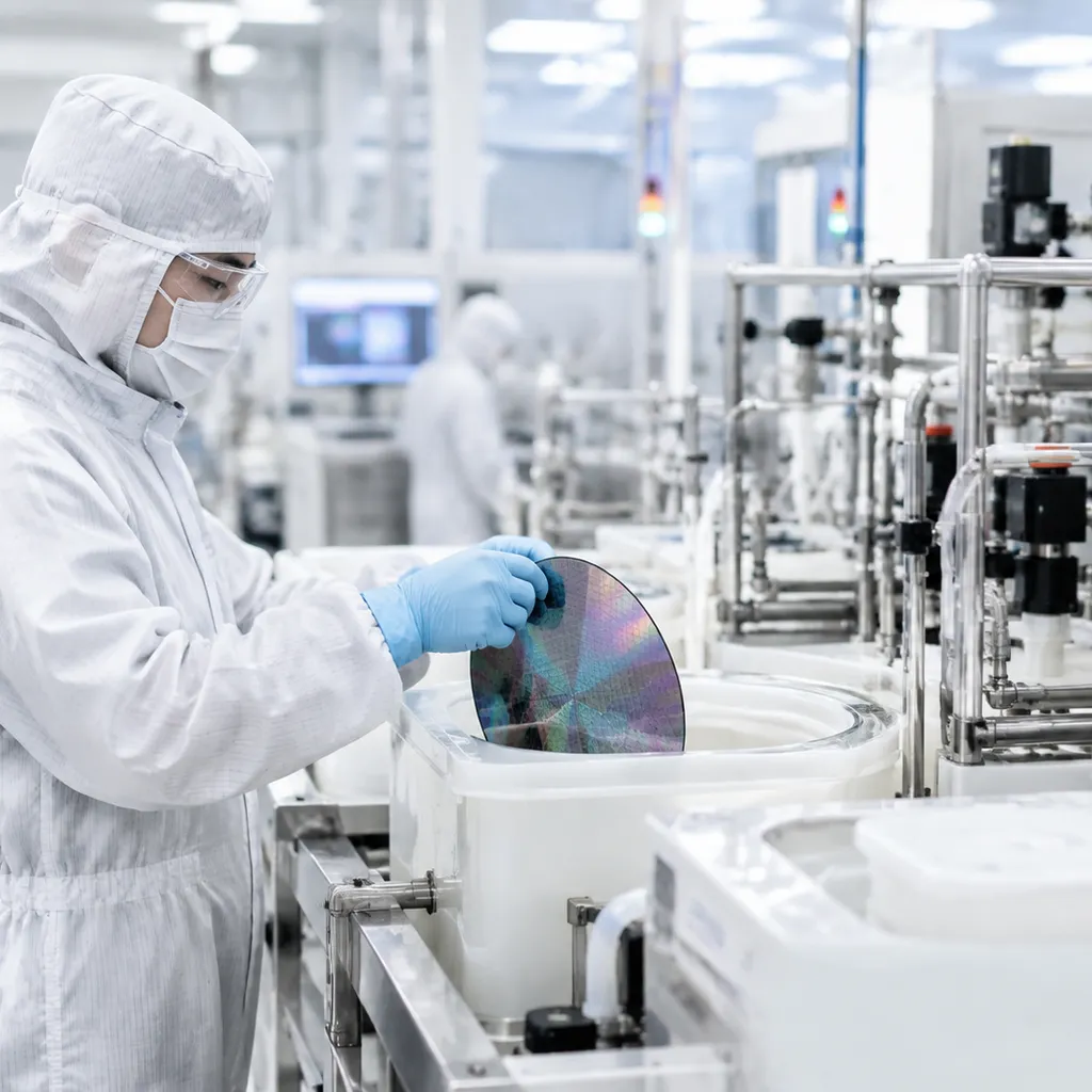
When wafer spacing drops down to approximately 2.38 mm, basic chemical immersion fails due to stagnation, trapped gas, and uneven acoustic fields. Delivering consistent yields across dense loads requires dedicated hardware engineering built into modern high-precision wet benches for semiconductor processing.
Chemical Bath Recirculation Weir Design and Flow Distribution
Tight spacing creates substantial fluid resistance between substrates. We eliminate flow dead zones by pairing precision bottom injection with dual or quad overflow weirs:
-
- Symmetrical Laminar Injection: Chemical manifolds running along the bottom of the process vessel distribute fresh, filtered etchant upward directly between the wafer faces.
- Continuous Perimeter Weirs: Fluid cascades continuously over the tank lip into outer catch basins, sweeping spent reactants away before concentration gradients form.
- Flow Velocity Balancing: Recirculation pumps are tuned to deliver sufficient turnover without generating excessive drag forces that could cause wafer chatter or mechanical deflection inside the cassette.
Megasonic Energy Propagation Without Acoustic Shadowing
In dense 50-wafer setups, adjacent substrates act as acoustic shields, creating dead zones where megasonic cleaning energy drops off sharply:
-
- Full-Coverage Transducer Plates: Transducer arrays mounted across the vessel floor ensure energy propagates evenly along the vertical plane of each wafer channel.
- Swept-Frequency Drivers: Sweeping frequencies across a narrow megasonic band prevents standing waves, eliminating localized hot spots that cause pitting while ensuring uniform boundary layer thinning from wafer center to edge.
Vertical Oscillation Mechanics for Bubble Clearance
Aggressive acid chemistries generate gaseous reaction byproducts. In high-aspect-ratio trenches and tightly spaced batches, these microbubbles cling to wafer surfaces, causing severe unetched defects.
-
- Servo-Driven Micro-Strokes: Programmable robotic lifters oscillate the wafer lot vertically within the chemical bath during the etch cycle.
- Boundary Layer Shearing: This controlled vertical motion continuously breaks surface tension, sweeping bubbles and spent chemical boundary layers out of narrow features.
Surface Tension Marangoni Drying Calibrated for Tight Wafer Spacing
Rinsing a high-capacity batch is only half the battle; drying dense wafer packs without watermark formation requires exact meniscus management:
-
- Controlled Meniscus Separation: As wafers slowly emerge from the ultra-pure water bath, a low-concentration isopropyl alcohol (IPA) vapor stream is injected right at the fluid line.
- Capillary Bridging Prevention: The resulting surface tension gradient (Marangoni effect) pulls water downward into the tank, preventing capillary retention and drying defects between tightly spaced wafer faces.
High-Capacity Batch Hardware Engineering Matrix
| Engineering Module | High-Capacity Batch Challenge | Hardware Solution |
|---|---|---|
| Fluid Recirculation | Stagnant chemical pockets in narrow gaps | Symmetrical bottom injection with 4-sided overflow weirs |
| Megasonic Array | Acoustic shadowing and carrier damping | Full-aperture swept-frequency bottom transducers |
| Wafer Lifter | Reaction gas entrapment in micro-trenches | Programmable vertical micro-oscillation profiles |
| Marangoni Dry | Capillary water trapping between close wafers | Controlled slow-pull mechanics with tuned IPA vapor delivery |
Fab Process Optimization: Operational Best Practices for Batch Sizing
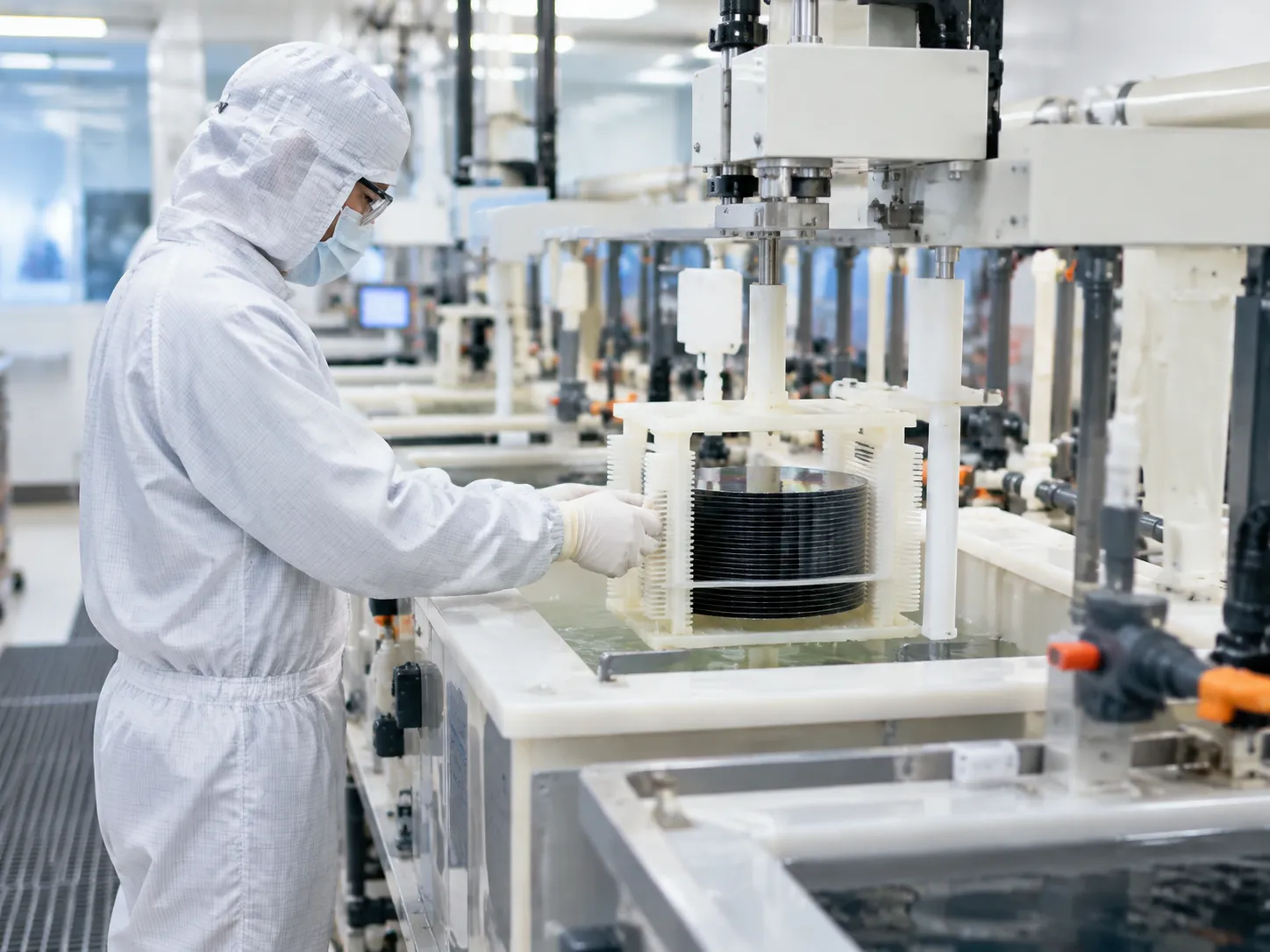
Determining the typical batch size wet etch semiconductor fab operations require is not just about tank volume. Real productivity depends on synchronized cycle times, strict bath chemistry management, and choosing the proper level of automation for your cleanroom line.
Balancing Etch, Rinse, and Dry Times to Prevent Robot Stalls
An automated wet bench is only as fast as its slowest tank. When running standard 25-wafer cassettes or 50-wafer half-pitch batches, scheduling mismatches create idle robot arms and chemical over-etch risks:
-
- The Drying Bottleneck: Etching might take only 3 to 5 minutes, but a thorough Quick Dump Rinse (QDR) and surface-tension Marangoni dry cycle often demands 8 to 12 minutes.
- Buffer Management: We design wet station process sequences with active queue tracking. If the dryer is occupied, the wet robot delays pulling the next batch from the chemical bath into the quench tank to prevent surface defects and uncontrolled etch stops.
- Dual-Transporter Efficiency: For high-volume lines, running dual transfer robots decouples chemical tank moves from rinse-and-dry transfers, keeping wet tanks loaded without dead time.
Bath Life Extension Through Dynamic Spiking and Inline Monitoring
Large wafer batches deplete active reagents rapidly. Relying on static chemical baths leads to drifting etch rates from the first run to the tenth run.
-
- Inline Concentration Tracking: We integrate inline sensors (such as acoustic velocity, NIR spectroscopy, or refractometers) to monitor acid or solvent ratios continuously.
- Dynamic Chemical Spiking: Instead of dumping an entire chemical bath when activity drops, automated metering pumps inject precise volumes of fresh spike chemicals.
- Etch Rate Stability: This continuous replenishment stabilizes chemical loading effects across full-capacity batches, ensuring uniform etch rates without dumping hundreds of liters of usable chemistry prematurely.
Semi-Automated Wet Stations vs. Fully Enclosed FOUP Automation
Matching batch size to tool automation prevents costly operational mismatches:
-
- Semi-Automated Benches: Best suited for R&D facilities, legacy lines running 150mm or 200mm wafers, and specialty substrates. In these environments, deploying a standalone wet process bench for semiconductor labs gives process engineers hands-on flexibility to adjust recipes without re-teaching complex factory automated material handling systems (AMHS).
- Fully Enclosed FOUP Systems: Mandatory for 300mm production fabs running high-density lots. Utilizing fully enclosed semiconductor wet processing systems for 300mm wafers isolates operators from aggressive chemistries, controls the local mini-environment, and sustains steady wafers-per-hour output through hands-off carrier loading.
Engineered Wet Bench Solutions by KOSEN SEMI
Modular Configurations for 25-Wafer and 50-Wafer Half-Pitch Lots
Fabs do not run on a one-size-fits-all model. We design our automatic wet bench systems with scalable process tanks and flexible robot end-effectors to support shifting production demands:
-
- 25-Wafer Standard Lots: Optimized for legacy carriers, R&D lines, and tight-tolerance critical gate strips where maximum fluid clearance is required.
- 50-Wafer Half-Pitch Batches: Configured for high-volume manufacturing (HVM) to double fab wafer throughput without doubling the equipment footprint.
- Flexible Footprints: Scalable layouts that accommodate diverse chemical recipes, from aggressive acid etching to precision solvent strips.
Advanced Bath Circulation Eliminating Stagnation and Boundary Layer Defects
Dense wafer spacing often leads to chemical loading effects and stagnant boundary layers. Our wet bench chemistry equipment integrates full-perimeter overflow weirs paired with bottom-up laminar chemical injection.
-
- Uniform Flow Velocity: Consistent fluid delivery across every wafer slot ensures predictable chemical replenishment from edge to center.
- Active Boundary Layer Disruption: Dynamic fluid velocity strips away spent reactants, maintaining stable etch rates across tightly packed 50-wafer profiles.
- Thermal and Concentration Stability: Continuous high-turnover inline recirculation prevents localized thermal hot spots during aggressive exothermic reactions.
Optimized Carrierless Transfer Designed to Lower Fab Chemical Consumption
Traditional cassettes trap significant chemistry, increasing drag-out contamination and DI water waste. We build automated carrierless immersion systems that pick, process, and transfer bare wafer arrays directly into the process baths.
-
- Minimizing Chemical Drag-Out: Removing the carrier structure cuts chemical carryover into rinse tanks by up to 70%.
- Faster Rinse Cycles: Reduced chemical loading allows quick dump rinsers (QDR) to achieve resistivity targets with fewer dump cycles.
- Lower Operating Costs: Fabs benefit from longer bath life, minimized chemical disposal expenses, and reduced overall cost of ownership (CoO).
Frequently Asked Questions About Wet Etch Batch Sizing
What is the typical batch size for wet etch in a semiconductor fab?
The typical batch size wet etch semiconductor fab facilities run depends directly on wafer diameter and fab architecture:
150mm and 200mm fabs: Standard runs use 25-wafer cassettes or paired 50-wafer dual-cassette setups.
300mm production fabs: Tools frequently process 50-wafer half-pitch batches loaded from two standard 25-wafer FOUPs into a single immersion tank.
Compound semiconductor fabs (GaAs, SiC, GaN): Smaller batches ranging from 10 to 25 wafers are common to protect high-value substrates and manage thermal reactivity.
Integrating a reliable wet station semiconductor equipment for wafer processing allows us to balance these lot volumes against tank chemical consumption and target line speed.
Why do 300mm fabs run 50-wafer half-pitch batches instead of 25 wafers?
Running 50 wafers in a half-pitch configuration cuts spacing between wafers by half, effectively doubling tool throughput without doubling bath footprint.
Key advantages include:
Higher Wafers Per Hour (WPH): Clears bottleneck etch and strip steps faster.
Lower Cost of Ownership (CoO): Halves the chemical volume and DI water demand per wafer.
Optimized Cleanroom Footprint: Keeps bath dimensions manageable while maximizing output from automated FOUP load ports.
How does wet etch batch size impact within-wafer non-uniformity (WIWNU)?
Packing wafers closer together alters boundary layer fluid dynamics. When chemical replenishment slows down between closely spaced substrates, the outer edges etch faster than the centers—a phenomenon known as the chemical loading effect.
To maintain tight WIWNU across dense lots, we rely on high-volume bath recirculation, side-overflow weirs, and controlled vertical oscillation to force fresh chemistry across every wafer surface evenly.
When is single-wafer processing preferred over high-capacity batch wet etch?
While high-capacity immersion dominates bulk stripping and non-critical cleans, choosing a single-wafer wet clean system for precision cleaning is better suited for:
Sub-nanometer boundary layers: Applications requiring ultra-tight across-wafer uniformity.
Zero lot-scrap tolerance: High-value front-end-of-line (FEOL) gates where losing an entire 50-wafer lot to a bath excursion is unacceptable.
Fast-reacting chemistries: Exotic formulations that degrade rapidly in open recirculating baths.
How do automated wet benches prevent acoustic shadowing during megasonic cleans?
In tightly spaced 50-wafer half-pitch batches, outer wafer edges can physically shield wafer centers from megasonic waves.
To eliminate acoustic shadowing and dead zones, we utilize:
Frequency sweeping transducers: Disrupts stationary standing waves within the tank fluid.
Continuous vertical oscillation: Moves the wafer lot across the acoustic beam during exposure.
Matched transducer spacing: Directs megasonic energy parallel to wafer planes, ensuring uniform particle release down deep aspect ratio structures.